

Imagine: only three months after the substation in a newly built industrial park was put into operation, the pillar insulator of 33kV line connected to the main transformer flashed in a rainstorm, causing a large area of the park to lose power, and the direct production loss was over a million dollars. The accident analysis report directly refers to the improper selection of insulators - without considering the local high humidity and industrial pollution superimposed on the special environment. This is not a fictional disaster, but the real cost of selection errors.
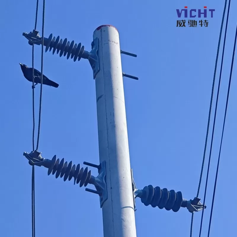
In a 33kV power transmission and distribution system, line pillar insulators are far from simple support components. They are the **silent guardian** that guarantees safe, stable and efficient power transmission. Improper selection, light is to increase maintenance costs, heavy is to cause power grid accidents. In this article, we will analyze the core elements of 33kV line insulator selection, to help you accurately match the project requirements, to avoid potential risks.
First, accurate locking core parameters: the cornerstone of selection
1. System voltage and insulation level:
Rated voltage (33kV): This is the basic requirement. Insulators must be designed for 33kV systems.
Rated Lightning Impulse Withstand Voltage (LIWV) & Rated Frequency Withstand Voltage (PW): the core index! They must strictly meet or exceed national standards (e.g. GB/T 8287.1, GB/T 19519) or international standards (e.g. IEC 60168, IEC 60273). For example:
Typical LIWV requirements for 33kV system insulators are typically in the 170kV to 200kV range.
PW is typically in the range of 70kV to 100kV.
Creepage Distance: The key to protection against dirt flashover! Refers to the shortest distance between two electrodes on the insulator surface. Selected according to the dirt classification of the installation area (IEC/GB dirt zone map):
Clean zone (I): ≥ 16 mm/kV (approx. 528mm)
Mildly dirty zone (II): ≥ 20 mm/kV (approx. 660mm)
Moderately dirty zone (III): ≥ 25 mm/kV (approx. 825mm)
Heavily dirty zone (IV): ≥ 31 mm/kV (approx. 1023mm)
Particularly heavily fouled zone (V): Special design or umbrella shape/material required.
Important: Coastal, industrial, foggy and humid areas must have higher creepage requirements. Selection failures are often due to underestimation of filth levels. *.
2. Mechanical Load Capacity:
Rated Mechanical Breaking Load (SML): The maximum vertical load (tensile, compressive or bending) that an insulator can withstand before failure.
Selection basis:
Conductor Load: Self-weight of the conductor, Tension (Horizontal Stall Distance, Vertical Stall Distance, Conductor Type/Cross Sectional Area, Maximum Wind Speed, Ice Cover Thickness).
Wind load: wind pressure acting on insulators and conductors (maximum design wind speed, insulator projection area).
Safety factor: Usually the design load is taken as more than 2.5-3 times of the maximum working load. Neglecting extreme weather (e.g. typhoons, ice storms) is a major hazard.
Typical range: SML ratings for commonly used pillar insulators for 33kV lines typically range from 4kN (~400kgf) to 12.5kN (~1250kgf) or higher.
3. Environmental adaptability: Extreme environments are the ultimate test case for insulators
Temperature: Tolerance of extreme maximum and minimum temperatures in the area of installation, with attention to low-temperature material brittleness (especially for porcelain insulators) and high-temperature aging (for composite insulators).
Humidity and fouling: directly affects creepage requirements (see previous section). High humidity exacerbates the effects of fouling.
Chemical corrosion: Chemical plants, coastal salt spray areas need to be selected
Conclusion: Accurate selection, constructing a safe line of defense for the power grid
The selection of pillar insulators for 33kV lines is a systematic work integrating electrical engineering, material science, environmental assessment and practical experience. It is not a simple parameter comparison, but an in-depth weighing of risks and cost-effectiveness over the whole life cycle of the project.
In the face of complex environments and stringent requirements, “enough” often means risk. Reserve margins in the choice of climbing distance, adhere to conservative calculations on the mechanical load, and trust reliable brands in the selection of materials - these seemingly increased costs of decision-making, but in fact is a strong dam against future losses of millions.
Every accurate selection is injecting a stable operation gene into the power grid. When the electric current passes through the mountains and plains silently, it is those insulators that can withstand the test of wind and frost that support every operation of modern society.